

General Electric IS230PCAAH1A SPEEDTRONIC Turbine Control
IS230PCAAH1A is part of the Speedtronic Mark V LM control panel, which provides connection and interface functions between the control engine with IO core and external hardware. This connection function helps to realize information exchange between different components within the control system, making the entire turbine control system work more coordinated.


Product Introduction
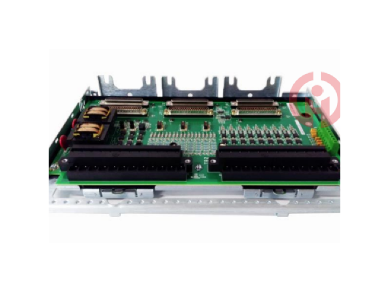
General Electric IS230PCAAH1A SPEEDTRONIC TURBINE CONTROL. The PCAA module has 120 Euro-style pluggable box terminals. The JGPA board mounted next to the module provides 48 shield terminal points (green) and 12 24 V DC output terminals (orange) for 4-20 mA transmitters using Euro-style box terminals. / Part Number: IS230STAIH2A Manufacturer: General Electric Series: Mark VIe Function: Terminal Board / General Electric Speedtronic Mark VIe IS230PCAAH1A Analog I/O Assembly The terminal board is part of the gas turbine control system / GE IS230PCAAH1A
Functional Description
This module is suitable for simplex, duplex and TMR systems. A single TCAT terminal board distributes signal inputs to one, two or three PCAA modules.
The shield ground and 24 V field power terminals of the adjacent JGPA board complement the terminals on the PCAA and TCAT. The module consists of a processor board shared by all Mark VIe distributed I/O boards, two application I/O boards, and a terminal board.
The entire module is considered a non-replaceable unit, and no assistance is provided to diagnose or replace the individual boards that make up the module.
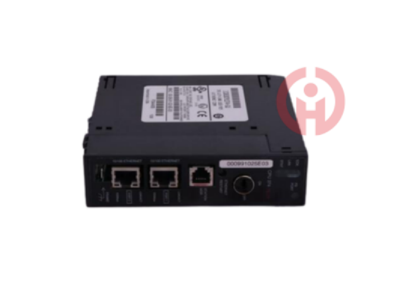
The module is powered by a 28 V DC power connector and two RJ45 Ethernet connectors. On the edge of the module, 120 Eurobox terminals provide field device I/O. Power is provided to the JGPA board via connector P4. The module connects to the TCAT via two 68-pin cables on connectors P1 and P2.
The PCAA signals are divided into two groups. The TCAT terminal board routes the signal inputs that can be fanned out from a single input to a single, dual, or TMR PCAA module. Signals dedicated to a single PCAA module are connected to the terminals. If fanned-out inputs are not required, the PCAA can be used without TCAT.
Connect the JGPA power to the P4 connector of the PCAA.
Connect the PCAA module to the optional associated TCAT terminal board using two 68-pin cables on connectors P1 and P2. Network connections connect the TCAT connectors. PR1 and PR2 connect to the R controller network, PS1 and PS2 connect to the S controller network, and PT1 and PT2 connect to the T controller network. To ensure proper grounding of the cables, fully install the cable mounting screws (finger tight only) into the PCAA and TCAT. If the cables are not securely fastened, the module may not be able to read the electronic ID on the TCAT and may degrade other signals.
Depending on the system configuration, connect one or two Ethernet cables. When only one IONet connection is used, the module can be used on either port. When dual connections are used, ENET1 is typically connected to the network associated with the R controller. The PCAA, on the other hand, does not care about the Ethernet connection and will negotiate correct operation over either port. If a TMR module is present, the network connection should correspond to the TCAT connection. For example, a PCAA module with R IONet connections should have cables connected to the TCAT PR1 and PR2 connectors.
Verify that the JGPA shield wire terminals are properly grounded. In most cases, the JGPA shield ground terminals are electrically connected to the metal plate to which the circuit board is mounted. The mounting then serves as the ground path for the terminal. In some applications, it is necessary to define a shield ground independent of the mounting metal plate. In these applications, the JGPA is mounted using hardware that isolates the circuit board from the metal plate. In these applications, it is critical to provide a suitable ground wire between one or more JGPA terminals and the desired shield ground potential.
Connect the module to power through the P5 connector and check the power and Ethernet status indicators.
If necessary, configure the I/O package using the ToolboxST application.
Processor Features
Two fully independent 10/100 Ethernet ports with connectors
Hardware watchdog timer and reset circuit
Internal temperature sensor
Status indicator LED
Electronic ID card and ability to read other board ID cards
Soft start/current limiter on input power connector
Local power supply, including sequencing and monitoring
Power management
The 28 V input circuit contains power management. The management function provides soft start to control the current surge during power up.
After power up, the circuit implements a fast current limiting function to prevent power disturbances in the module from propagating back into the 28 V power system.
The green PWR indicator is on when power is on and operating normally. The indicator will be on if the current limiting function is enabled
The IS230PCAAH1A REV A is a PCCA core analog module manufactured and designed by General Electric and is part of the VIe series used in GE's distributed gas turbine control systems. The core analog (PCAA) module and the associated core analog (TCAS and TCAT) terminal boards provide most of the analog signal I/O required to operate the gas turbine. The PCAA and TCAT provide thermocouple inputs, 4-20 mA current loop I/O, seismic inputs, linear variable differential transformer (LVDT) excitation and inputs, pulse rate inputs, and servo coil outputs. The PCAA can be applied to simplex, duplex, and TMR systems. A single TCAT terminal board routes signal inputs to one, two, or three connected PCAA modules. Shield ground and 24 V field power terminals on adjacent JGPA boards supplement the terminals on the PCAA and TCAT.
The PCAA consists of a processor board common to all Mark VIe distributed I/O, two application I/O boards, and a terminal board. The entire module is considered a non-replaceable unit, and no support is provided for diagnostics or replacement of the individual boards that make up the module. Inputs to the module are through dual RJ45 Ethernet connectors and 28 V DC power connector P5. Field device I/O is through 120 Eurobox terminals on the edge of the module. Power to the JGPA board is through connector P4. The module's connection to the TCAT is via two 68-pin cables on connectors P1 and P2.
Installation:
Connect the PCAA module to the optional associated TCAT terminal board using two 68-pin cables on connectors P1 and P2. The connectors on the TCAT mate via network connections. PR1 and PR2 connect to the PCAA connected to the R controller network, PS1 and PS2 connect to the PCAA connected to the S controller, and PT1 and PT2 connect to the PCAA connected to the T controller.
The cable mounting screws must be fully installed (finger tight only) into the PCAA and TCAT to ensure proper grounding of the cables. Failure to secure the cables may prevent the PCAA from reading the electronic ID on the TCAT and may degrade other signals.
Insert one or two Ethernet cables depending on the system configuration. When using a single IONet connection, the module will operate correctly through either port. If dual connections are used, standard practice is to connect ENET1 to the network associated with the R controller.
However, the PCAA is not sensitive to Ethernet connections and will negotiate for correct operation over either port. If a TMR PCAA module is present, the network connection should match the connection to TCAT. For example, a PCAA module with R IONet connections should have cables connected to the TCAT PR1 and PR2 connectors.
Operation:
The PCAA module consists of four separate circuit boards in a single physical assembly. The module is considered a least replaceable unit due to the difficulty in isolating a fault to a single circuit board. The module is not intended for replacement of individual circuit boards. The TCAS accepts bulk 28 V control power through the P5 connector. It then provides power to the JGPA board at the input cable shield termination location through connector P4. The TCAS provides the IS200TCAT terminal board cable with P1 and P2 68-pin connectors. Internally to the module, the TCAS terminal board routes the signals to the connectors for the BCAA and BCAB analog processing boards.
PCAA Processor:
High-speed processor with RAM and flash
Two fully independent 10/100 Ethernet ports with connectors
Hardware watchdog timer and reset circuit
Local ambient temperature sensor
Infrared serial communication port
Status indicator LED
Electronic ID card and ability to read other on-board ID cards
Extensive programmable logic to support acquisition boards
Input power connector with soft-start/current limiter
Local power supply, including sequencing and monitoring
I think you'll find our product offers great value for money!
It's my pleasure to introduce our latest product, which will be a great addition to your current offerings!
We're thrilled to introduce you to our latest product, which we believe will meet your needs perfectly!
We believe this product can help to expand your market share. We look forward to the opportunity to work with you!
We sincerely welcome your calls and consultations and provide you with quality service 24 hours a day!
· Many products are not yet on the shelves please contact us for more products.
· If there is inconsistency between the product model and the display picture, the model shall prevail, please contact us for specific product pictures, we will arrange to take pictures in the warehouse to confirm!
.Technical Team Service Hotline:wujinghan102@gmail.com +86 13376990653
csyili980622@gmail.com +86 13306931261

