

GE DS200TCTGG1AFF Simplex Trip Board
The DS200TCTGG1AFF is a simplex trip board that was originally manufactured for General Electric's Mark V series of turbine control systems. Since this series was discontinued after its initial release, it is now considered a legacy product. Although the Mark V is a legacy series, it is one of the last in the GE product line to feature the patented Speedtronic control system technology designed for gas, steam and wind turbine control and management.


Product Introduction
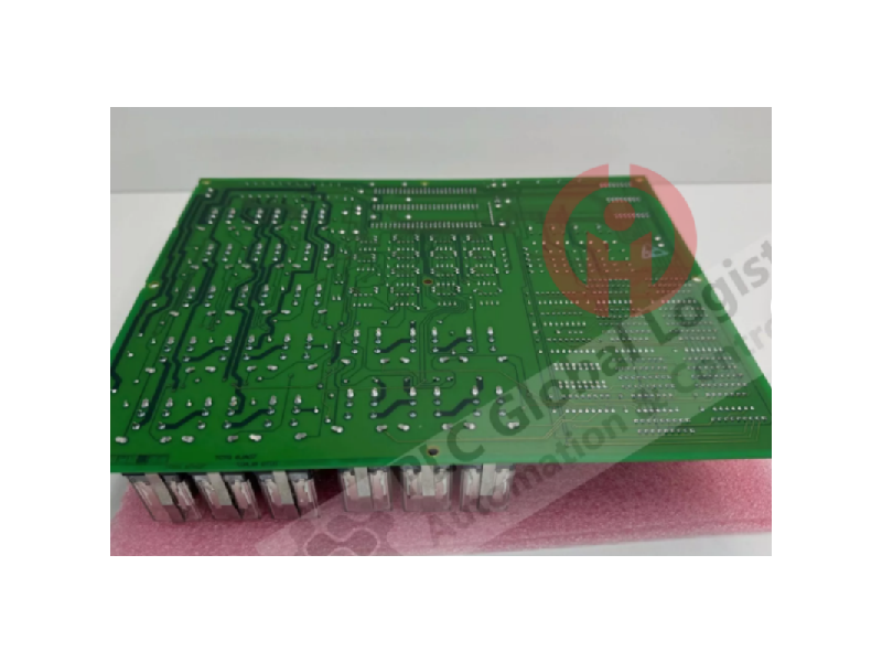
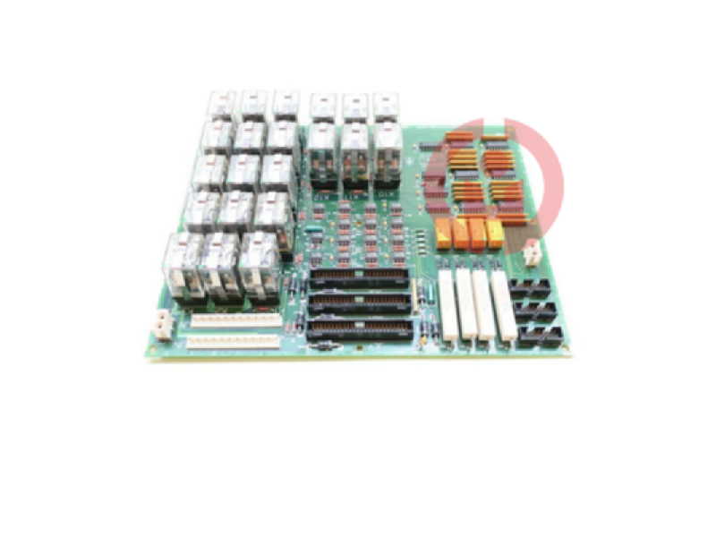
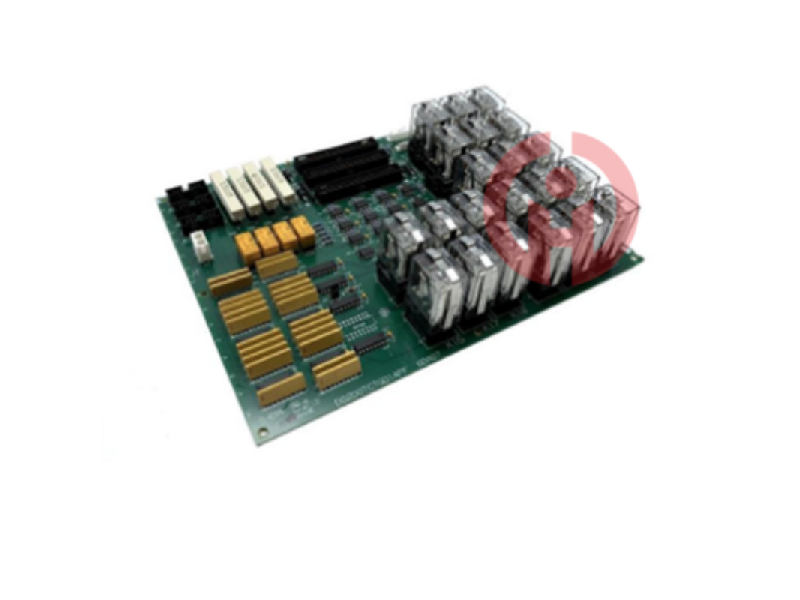
DS200TCTGG1AFF is a simplex trip board that is part of the GE Speedtronic Mark V gas turbine control system. The simplex trip board is used as a medium duty trip board. There are 21 plug-in relays on the simplex trip board DS200TCTGG1AFF. The board also includes three 50-pin connectors and two 12-pin connectors. JLY, JLX, and JLZ are the IDs assigned to the 50-pin connectors. JN and JM are the IDs assigned to the 12-pin connectors. The IDs of the 21 plug-in relays start with K and end with a number. The numbers increase in sequence starting from 1. K1, K5, K10, and K21 are some of the IDs. Metal straps hold the relays in place when they are snapped into the board. Remove the metal straps from the relays and then pull them out of the connector to remove them. Align the relay with the connector and press it into the connector to install it. After that, clip one end of the metal strap onto the connector, place the metal strap on top of the relay and clip the other end of the metal strap onto the other side of the connector. WOC has the largest inventory of Speedtronic Mark V Controls spare parts and we can repair your faulty DS200TCTGG1AFF and offer a 12 month warranty. WORLD OF CONTROLS can also supply unused and refurbished DS200TCTGG1AFF with a 24 month warranty. Our team of experts is on call 24/7 to assist with your DS200TCTGG1AFF needs. WOC's sales team is happy to assist you with any of your automation needs. Please contact our staff by phone or email for pricing and availability of any parts and repairs.
About DS200TCTGG1AFF
This DS200TCTGG1AFF simplex trip panel was originally manufactured for General Electric's Mark V Turbine Control System series, which is now considered a GE Legacy series as it was ultimately discontinued a few years after its initial release. This DS200TCTGG1AFF Printed Circuit Board or PCB for short, Mark V Series, while existing as a GE Legacy Series, is also considered one of the final GE Mark Series utilizing the patented Speedtronic control system technology and has specific applications in control and management systems for gas, steam and wind turbine automatic drive assemblies. This DS200TCTGG1AFF PCB is used as a simplex trip board in its Mark V Series automatic drive assemblies, as evidenced by the presence of this description in the original Mark V Turbine Control System Series Guidance Document. This DS200TCTGG1AFF PCB is not the original simplex trip board in the Mark V Series; that would be the DS200TCTGG1 parent PCB lacking three major revisions for this DS200TCTGG1AFF product.
Hardware Tips and Specifications
Like any Mark V Series assembly sold here, this DS200TCTGG1AFF PCB utilizes its own set of functional hardware components and component specifications. The GE Simplex Trip Board DS200TCTGG1AFF is populated with 21 plug-in relays. It also has three 50-pin connectors and two 12-pin connectors. The IDs assigned to the 50-pin connectors are JLY, JLX, and JLZ. The IDs assigned to the 12-pin connectors are JN and JM. Given the low general availability of original instruction manual material for this DS200TCTGG1AFF device, the DS200TCTGG1AFF functional product number itself can be considered a good source of hardware identification for the original DS200TCTGG1AFF board, starting with its DS200 series label, which has a dual DS200TCTGG1AFF board naming convention. The DS200 series label at the very beginning of the DS200TCTGG1AFF functional product number describes the status of this device as both a domestically produced printed circuit board and a PCB with the common Mark V Turbine Control System series component style. Some other DS200TCTGG1AFF board specific details embedded in the DS200TCTGG1AFF functional product number include this DS200TCTGG1AFF PCB:
TCTG functional product abbreviation
General style of PCB coating
First group Mark V series product grouping
A-level functional product revision
F-level secondary functional product revision
F-level artwork configuration revision
The 21 plug-in relays in this DS200TCTGG1AFF board assembly have IDs prefixed with K and ending with a number. These numbers start at 1 in sequence. Some of the IDs are K1, K5, K10, and K21. The relays snap into place on the board and are held in place by metal straps. To remove the relay, remove the metal strap and pull the relay out of the connector. To install the relay, align it with the connector and press it into the connector. Then, clip one end of the metal strap to the connector, place the metal strap on top of the relay, and then clip it to the other side of the connector. To replace the relay, the GE Simplex Trip Board DS200TCTGG1AFF must be removed from the drive. Speak with an engineer or installer who is familiar with drive installation and the power to which the drive is connected. Disable power by disconnecting fuses or other means as needed. Test the current flow inside the drive using a test device before proceeding. Disconnect the cables from the board and make a diagram of the cable locations so that the cables can be connected to the correct connectors when the board is reinstalled.
This DS200TCTGG1AFF Simplex Trip Board was originally manufactured for General Electric's Mark V line of turbine control systems and is now considered a GE Legacy line due to its eventual discontinuation of production a few years after its initial release. This DS200TCTGG1AFF Printed Circuit Board (PCB for short) is part of the larger Mark V series and while it exists as a GE Legacy line, it is also considered one of the final GE Mark lines to feature the patented Speedtronic control system technology and has specific applications in control and management systems for automated drive components for gas, steam, and wind turbines.
Specific Details
TCTG Functional Product Abbreviations
General Style of PCB Coating
First Group Mark V Series Product Groupings
Class A Functional Product Revisions
Class F Secondary Functional Product Revisions
Class F Artwork Configuration Revisions
DS200TCTGG1A is a Turbine Trip Board (TCTG) developed by General Electric. It controls the fuel shutoff section of the turbine and is located in position 4 of the core. On the TCTG board, there are two different trip relay types available for the fail-safe fuel valve function. Both the Primary Trip Relay (PTR) and the Emergency Trip Relay (ETR) are available. The PTR is controlled by the CSP and communication errors. The ETR is managed by the TCEA board in the core and a 2/3 vote is required for an emergency trip. A hardwired trip push button will shut off the 24 V DC power to the PTR and ETR relays and initiate a trip. The TCTG board also houses a sync relay.
DS200TCTGG1A Configuration
Hardware
On the TCTG board, there is only one hardware jumper. The emergency overspeed servo clamp is J1. Activate the jumper to open servo valves 1-4. This jumper is required to apply 24 V DC to the servo outputs. The actual relays are located on the TCQC board.
Software
The TCTG board does not have any software configured.
DS200TCTGG1A Connector
J7W - The 125 V DC power from the TCPD board is distributed throughout the core via J7W.
JDR - JDR relays K10, 13, 16, and 19 after reading the PTR trip signal from the TCQA board in the core. Reads the sync command from the TCQA board in the core. Reads the bus and generator signals from the PTBA board. On the TCTG board, JDR, JDS, and JDT are all daisy-chained together.
JDS - Relays K11, 14, 17, and 20 and reads the PTR trip signal from the TCQA board in the core. Reads sync commands from the TCQA board in the core. Reads bus and generator signals from the PTBA board. On the TCTG board, JDR, JDS, and JDT are all daisy-chained together.
JDT - Reads relays K12, 15, 18, and 21 on PTR trip signals from the TCQA board in the core. Reads sync commands from the TCQA board in the core. Reads bus and generator signals from the PTBA board. On the TCTG board, JDR, JDS, and JDT are all daisy-chained together.
JLX - Reads core-based ETR trip signals. The JLX connector powers K5 and K8 of the ETR relays. Provides energy to the 24 V DC protection bus.
JLY - Use the JLY to read the ETR trip signals from the core. The JLY connector powers ETR relays K4 and K7. Provides energy to the 24 V DC protection bus.
JLZ - Reads ETR trip signals from P1 core Z via JLZ. The JLZ connector powers K6 and K9 of the ETR relay. Powers the 24 V DC protection bus.
JN - Reads and writes signals to the PTBA terminal block of the P1 core. Breaker closed signals, hardwire trip signals, and alarm horn signals are some examples of these signals.
JM - Reads and writes signals to the PTBA terminal block of the P1 core. Emergency trip signals and breaker closed signals are examples of these signals.
JT - Not commonly used.
ETR Relay
The trip signals for the ETR relay are generated by TCEA boards X, Y, and Z in the P1 core. The signals are written to the TCTG board via the JLX/Y/Z connections. To decide if it should trip, the ETR relay does a hardware level 3-out-of-2 vote. By opening and closing a string of related contacts on the TCTG board, the device will trip if two of the three relays call for a trip. High voltage shaft overspeed and rapid deceleration, low voltage shaft overspeed and rapid deceleration, and cross trip are signals that will trip the ETR relay. The trip signal is then written to the PTBA terminal board using the JM connector.
Generator Breaker Closing Circuit
The STCA board in R1 and the TCEA board in the P1 core are the sources of the signal to close the generator breaker. The TCEA board uses the PT signal from the PTBA terminal board for the automatic synchronization calculation and transmits the permission signal to close the breaker. The STCA board in the R1 core simultaneously calculates the synchronization permission (sync check) and transmits the permission to close the breaker. The TCTG board votes two to three for the automatic synchronization signal. If R1 provides the sync check signal and two of the three automatic synchronization signals have been received, the TCTG board will allow the breaker to close.
DS200TCTGG1A Manual and External Trip Circuit
To initiate a trip when the contacts are open, normally closed contact inputs can be plugged into the PTBA terminal board. Examples of these include emergency stop buttons. These signals trigger the K22, 23, 24, and 25 relays, which are read by the JN connection and written to the TCTG board. These relays are referred to as 4 relative to the ANSI standard device number for the main protection. When 4 trips, the PTR and ETR relays trip because they are connected to the 24 V DC protection bus, which is de-energized when 4 trips. The TCEA board normally logs events back to the control engine and monitors the hardwired trip signals 1 to 3 for emergency stops.
DS200TCTGG1A Features
There are 21 plug-in relays in it. In addition, it has two 12-pin connectors and three 50-pin connectors. The 50-pin connectors are assigned IDs JLY, JLX, and JLZ.
The 12-pin connectors are assigned IDs JN and JM. The 21 relays on the board are very delicate and require extra care.
Due to the electromechanical structure of the relays, the relays can be easily damaged. Circuit boards can also be damaged by static buildup. The 50-pin connector is connected via a ribbon cable. There are multiple 50-pin connectors, so when replacing circuit boards, there is a risk of improperly connecting the 50-pin connector.
Improper installation can increase the time the drive is offline and may also increase downtime for other nearby equipment. Before removing the drive, turn off the power and check how the wires are connected to the circuit board to prevent any delays.
The 21 plug-in relays have IDs that start with K and end with a number. The numbers are listed in sequence, starting at 1. K1, K5, K10, and K21 are just a few of the IDs.
Product Features
Part Configuration:
Comes with 21 plug-in relays with IDs that start with K and end with a number, starting at 1, such as K1, K5, K10, and K21.
Has 3 50-pin connectors and 2 12-pin connectors, where the 50-pin connectors are numbered JLY, JLX, JLZ and the 12-pin connectors are numbered JN, JM.
Design features:
Modular design: The relay output board adopts modular design, which can easily replace or expand the relay channel to meet different application requirements.
High reliability: Provides high reliability for applications that require stable and reliable relay operation, such as safety-critical systems.
High current and voltage capacity: Can be used to control various types of loads, including high-power equipment.
Troubleshooting function: Helps users identify and troubleshoot problems in relay channels.
Other functions:
Can be equipped with communication interfaces for integration with other systems to achieve remote monitoring and control.
With appropriate protection levels to adapt to different industrial environments, including factories and outdoor applications.
Application areas
GE DS200TCTGG1AFF single trip door board is widely used in the power industry, oil and gas industry, chemical industry and other fields that require steam turbine control systems.
I think you'll find our product offers great value for money!
It's my pleasure to introduce our latest product, which will be a great addition to your current offerings!
We're thrilled to introduce you to our latest product, which we believe will meet your needs perfectly!
We believe this product can help to expand your market share. We look forward to the opportunity to work with you!
We sincerely welcome your calls and consultations and provide you with quality service 24 hours a day!
· Many products are not yet on the shelves please contact us for more products.
· If there is inconsistency between the product model and the display picture, the model shall prevail, please contact us for specific product pictures, we will arrange to take pictures in the warehouse to confirm!
.Technical Team Service Hotline:wujinghan102@gmail.com +86 13376990653
csyili980622@gmail.com +86 13306931261

