

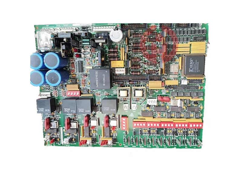
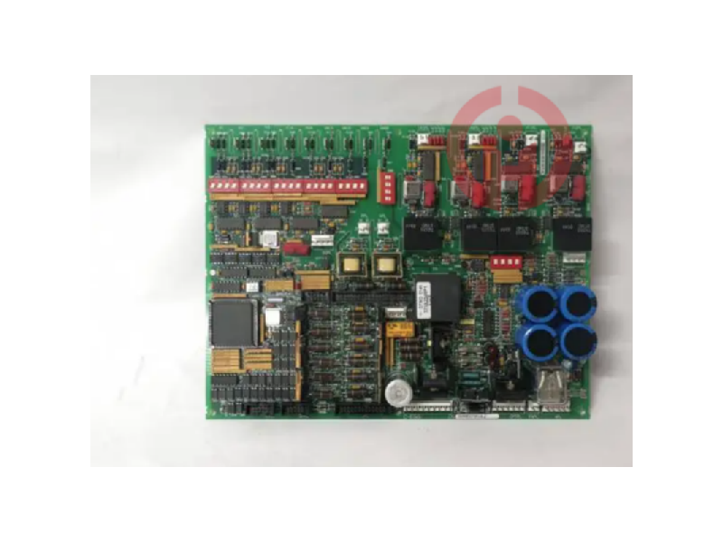
GE DS200DCFBG1BLC Mark V | Speedtronic Power Supply Board
The DS200DCFBG1BLC is a DC feedback power board designed for the General Electric Mark V Series Turbine Control Systems. This power board is specifically designed to provide system control level power to a wide range of drives including those found in wind, steam and gas turbine applications. It is compatible with a range of GE exciters and drives, ensuring seamless integration with multiple systems in the Mark V Series.


Product Introduction
The DS200DCFBG1BLC is a power board designed by General Electric for the Mark V series optional and replacement boards. Members of this family are cross-compatible with many GE brand exciters and drives. The DC2000, AC2000, CB2000, ME2000, and FC2000 drives can all accept this power board. This card provides system control level power to the drive to which it is installed, as well as providing power for the cabinet fans. The AC input source rating for this board is 38 to 115 VAC. The frequency range that accompanies this VAC is 0 to 500 kHz, depending on the strength of the input voltage. While this DS200DCFBG1BLC printed circuit board itself can be defined as a power board, the original power board developed in the Mark V turbine control system family was the DS200DCFBG1 power board, which lacks three important functional revisions of this DS200DCFBG1BLC product. As its extended name implies, this DS200DCFBG1BLC power board's larger Mark V Turbine Control System family has specific applications in the management and control systems of wind, steam and gas turbine automated drive components.
Technical Specifications
Manufacturer: GE General Electric
Series: Mark V
Part Number: DS200DCFBG1BLC
Functional Description: DC Feedback Power Board
AC Input Voltage: 38 to 115 VAC
Input Frequency: 0 to 500 kHz (depending on input voltage strength)
Drive Compatibility: DC2000, AC2000, CB2000, ME2000, FC2000
Test Points:
P5 +5V DC Power Test Point
DCOM 0 V Test Signal Common Reference Point
P15 +15 V DC Power Test Point
N15 -15 V DC Power Test Point
ACCT DCFB to SDCC ACCT Signal Test Point
Hardware Functions
Supervisory Circuitry: Includes AC and DC monitoring circuitry for continuous feedback.
Control Circuit: Has control stage power supply circuit, motor excitation power supply circuit, drive circuit.
Indicator: Equipped with two LED indicators and one neon indicator to communicate the board status and provide diagnostic feedback.
Protection: Three fuses protect the board from surges and interruptions to ensure reliable operation.
Configurability: The board contains twelve jumpers and seven DIP switches, allowing customization to meet external system requirements.
Environment and Compliance
Application: Mainly used in turbine control systems for wind power, steam power, and gas turbine drive components.
Power Supply: AC input with a wide voltage range (38 to 115 VAC).
Protection: Designed for industrial environments, with surge protection and power interruption protection.
Hardware Tips and Specifications
The DS200DCFBG1BLC contains many complex circuit systems designed to power most drives. The card includes AC and DC monitoring circuits, control stage power supply circuits, motor excitation power supply circuits, and drive circuits. The user can configure the twelve jumpers and seven DIP switches on the card to meet any external requirements. The board status is communicated to the user through onboard indicators. Two LED indicators and a neon indicator are built into the card to provide the user with important diagnostic and status information. The board's three fuses are protected, ensuring that any major interruptions or surges will not disrupt the flow of current on the DS200DCFBG1BLC board or its larger Mark V Series AutoDrive components. Be sure to monitor voltage levels regularly using the board's five integrated test points. Fortunately, the specific function of each of the DS200DCFBG1BLC product's five test points is described in the DS200DCFBG1BLC instruction manual embedded in the Manuals tab above. The test points for this DS200DCFBG1BLC power board include:
P5 +5 V DC power test point
DCOM 0 V test signal common reference point
P15 +15 V DC power test point
N15 -15 V DC power test point
ACCT DCFB to SDCC ACCT signal test point
All of the above test points in this DS200DCFBG1BLC board assembly are named by their factory printed naming labels, specific voltage ratings, and functional combinations of the DS200DCFBG1BLC printed circuit board and its larger Mark V Turbine Control System Series automated drive assembly. The DCFB and SDCC boards accessed by the ACCT test points for this DS200DCFBG1BLC product can also be purchased and serviced here in a variety of different revisions. It is critical that the installation parameters provided with the DS200DCFBG1BLC and drive are followed. These guidelines will ensure that the board and the system it is installed in will operate as expected. In general, this DS200DCFBG1BLC printed circuit board should be considered an electrostatically sensitive product that may have lethal surface voltages during or after normal functional use. Refer to the series manual as well as the device datasheet for wiring and installation guidelines. Technical support for all Mark V Series boards is initially provided by the manufacturer, General Electric. The trusted team at AX Control is happy to help you with all of your DS200DCFBG1BLC needs. Please contact a member of our team by phone or email for pricing and availability of all parts and repairs.
Frequently Asked Questions About the DS200DCFBG1BLC
How much input power does the DS200DCFBG1BLC receive from the CPT?
The DS200DCFBG1BLC receives 38 and 115 VAC (24 VDC) input power from the control power transformer (CPT) connected to the DS200DCFBG1BLC.
Where can I find a description of the connector pins on the DS200DCFBG1BLC?
The DS200DCFBG1BLC receives and sends input and output signals/power through 18 header connectors and 9 plug-in connectors. Table 6-22 in the DS200DCFBG1BLC manual (Manual GEI-100028) provides a description of each connector. The table in the manual identifies the DS200DCFBG1BLC connectors by pinout, term, and description. Figure 1 in the DS200DCFBG1BLC manual (i.e., the GE Industrial Systems Power Supply Manual) also shows the location of the connectors with a DS200DCFBG1BLC board layout diagram.
How many jumpers does the DS200DCFBG1BLC have?
The DS200DCFBG1BLC has 12 configurable jumpers. Location of jumpers The jumpers on the DS200DCFBG1BLC are jumpers JP1-JP14, but jumpers JP13 and JP14 have been removed on the DS200DCFBG1BLC. You can find the location of the DS200DCFBG1BLC jumpers in manual Figure 1, and you can find the description of the jumpers on the DS200DCFBG1BLC in manual Table 1 (manual GEI-100028). For a copy of the manual, please request the DS200DCFBG1BLC manual.
What is Stab P1A on the GE DS200DCFBG1BLC board?
Stab P1A on the DS200DCFBG1BLC is one of the stabilizing terminal connectors of the DS200DCFBG1BLC, and is the connector for the DC bridge positive voltage of the DS200DCFBG1BLC.
GE DS200DCFBG1BLC Digital Controller
However, they can range from 0 to 500 kHz. Many circuits on the board work together to power the board and the installed drive. Motor field power, drive, AC/DC monitoring and control level power circuits are all part of the DS200DCFBG1B. The board's 12 jumpers and 7 DIP switches provide the user with system configuration choices. Two LEDs and an indicator light on the board are used to display fuse switch diagnostics. Three protection fuses ensure that power is not interrupted. Ten thousand test points on the board can be used to dry check the voltage. Please refer to the equipment manual and data sheet for detailed guidelines on board wiring and installation. Originally, the manufacturer General Electric provided technical support for this board and the Mark V series.
The DS200DCFBG1BLC is the power board planned by General Electric for the Mark V series optional and replacement board. Members of this series are cross-compatible with many GE brand exciters and drives. The DC2000, AC2000, CB2000, ME2000 and FC2000 drives can all accept this power supply board. The card supplies system control level power to the drives it is equipped with and also powers the chassis fans. The source AC input rating of the board is 38 to 115 VAC. The frequency scheme that accompanies this VAC can be from 0 to 500 kHz, depending on the strength of the input voltage.
The DS200DCFBG1BLC contains a lot of complex circuitry designed to power most drives. The card includes AC and DC monitoring circuits, control level supply circuits, motor excitation supply circuits, and drive circuits. The user can configure 12 jumpers and 7 DIP switches on the card to meet any external requirements. The board status is communicated to the user through onboard indicators. Two LEDs and a neon light are built into the card to provide the user with important diagnostic and status information. The board is protected by three fuses to ensure that current is not sustained due to a connection or surge. Be sure to use the five test points integrated on the board.
I think you'll find our product offers great value for money!
It's my pleasure to introduce our latest product, which will be a great addition to your current offerings!
We're thrilled to introduce you to our latest product, which we believe will meet your needs perfectly!
We believe this product can help to expand your market share. We look forward to the opportunity to work with you!
We sincerely welcome your calls and consultations and provide you with quality service 24 hours a day!
· Many products are not yet on the shelves please contact us for more products.
· If there is inconsistency between the product model and the display picture, the model shall prevail, please contact us for specific product pictures, we will arrange to take pictures in the warehouse to confirm!
.Technical Team Service Hotline:wujinghan102@gmail.com +86 13376990653
csyili980622@gmail.com +86 13306931261

