


Product Introduction
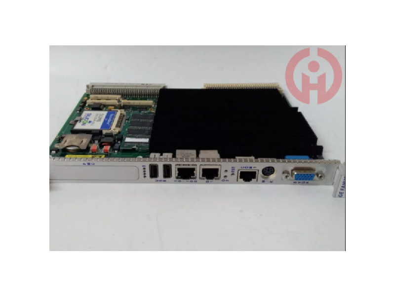
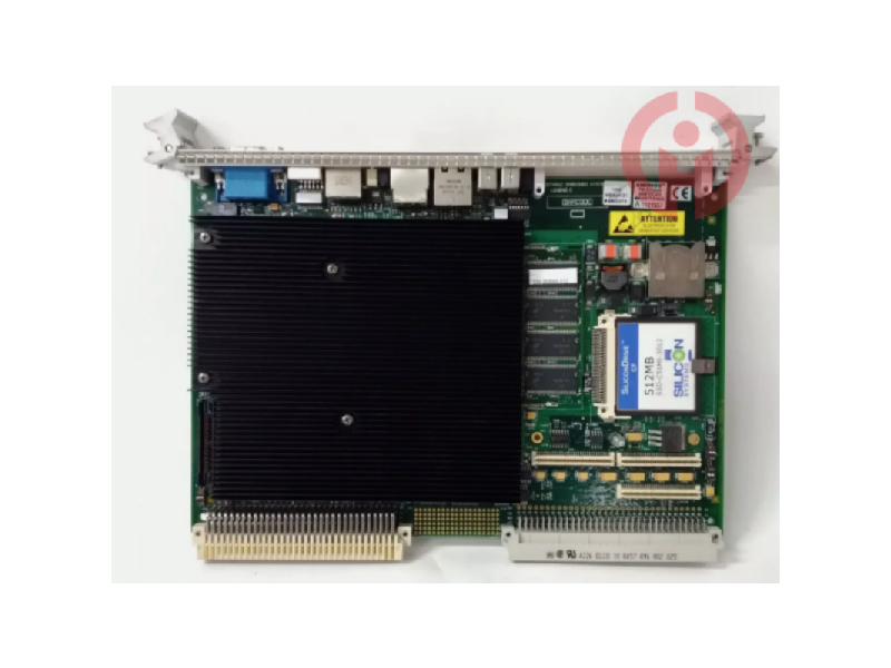
GE VMIVME-7807 | VMIVME-017807-414001 | 350-0001007807-414001D. The GE VMIVME-7807 (also known as the VMIVME-017807-414001) and the 350-0001007807-414001D are both names of the same product, GE's variable frequency drive (VFD).
Variable frequency drives (VFDs) are used to control electric motors, reducing energy consumption and increasing efficiency. By varying the frequency of the power supplied to the motor, the speed of the motor can be precisely controlled. (Click to view related products: VMIVME-7750, VMIVME-7614)
The GE VMIVME-7807 is a three-phase variable frequency drive rated at 780 kW. It has an operating temperature range of -40 to +85 °C and is designed for hazardous location applications.
This VFD has a variety of features, including:
Direct digital control (DDC) for precise speed control
Modbus RTU and ASCII communication protocols
Built-in diagnostics and protection features
Wide operating range of 50 Hz to 60 Hz.
Designed to interface with the Mark VIe system, this board is capable of accepting up to 24 contact inputs. These inputs are supplied by an externally supplied 24, 48, or 125 V DC nominal excitation voltage. This voltage supply enables the STCI to effectively interface with a wide variety of sensors, switches, or devices that generate contact signals, allowing the system to accurately receive and process these inputs.
A key feature of the board is its implementation of noise suppression mechanisms. These mechanisms are specifically designed to protect the system from potential damage caused by surges and high-frequency noise. By mitigating these unwanted signals, the board ensures the integrity and reliability of the contact inputs received, thereby enhancing the overall robustness and performance of the system.
In effect, it acts as a key interface between the external device or sensor and the Mark VIe control system. It enables seamless integration of contact-based signaling into a wider control scheme, enabling monitoring, control and response to a wide range of operating parameters in industrial environments.
Its DIN rail or flat mount compatibility enhances installation flexibility and allows for easy integration into existing control panels or systems. This design feature simplifies deployment and maintenance, helping to improve the overall efficiency and availability of the control system.
The installation process involves several key steps and considerations to ensure proper installation, wiring and functionality within the control system. The STCI is mounted with a plastic insulator on a sheet metal carrier, which can then be fastened to a DIN rail. Alternatively, the positive insulator can be optionally mounted on a sheet metal assembly, which can then be securely bolted into the cabinet.
Mounting Options:
DIN Rail Mount: This assembly, combined with a plastic insulator, is typically mounted on a sheet metal carrier designed to attach to a DIN rail. This approach allows for convenient installation within a control panel or equipment rack utilizing the DIN rail system commonly found in industrial environments.
Cabinet Bolt Mount: Alternatively, the STCI, along with the insulator, can be mounted on a sheet metal assembly designed for cabinet mounting. The assembly is then securely fastened within the cabinet, providing another method of housing the board.
Contact Input Wiring:
The contact inputs are wired directly to the terminal block. This wiring process involves connecting the external device or sensor that generates the contact-based signal to the terminal block. Typically, 18 AWG wires are used to connect the contact inputs.
These wires are selected based on their proper gauge size, ensuring proper conductivity and compatibility with the terminal block.
Shield Termination:
To prevent electromagnetic interference (EMI) or noise, the shields associated with the wiring should be properly terminated.
The shields are typically directed to a separate bracket or terminal point, ensuring proper grounding and isolation from the signal transmission lines.
Designed to interface with the Mark VIe system, the board is capable of accepting up to 24 contact inputs. These inputs are supplied by an externally supplied 24, 48, or 125 V DC nominal excitation voltage. This voltage supply allows the STCI to effectively interface with a variety of sensors, switches, or devices that generate contact signals, allowing the system to accurately receive and process these inputs.
A key feature of the board is the implementation of its noise suppression mechanism. These mechanisms are specifically designed to protect the system from potential damage caused by surges and high frequency noise. By mitigating these unwanted signals, the board ensures the integrity and reliability of the contact inputs received, enhancing the overall robustness and performance of the system.
In effect, it acts as a critical interface between external devices or sensors and the Mark VIe control system. It enables seamless integration of contact-based signals into a wider control scheme, enabling the monitoring, control and response of a wide range of operating parameters in industrial environments.
Its DIN rail or flat mount compatibility enhances installation flexibility, allowing for easy integration into existing control panels or systems. This design feature simplifies deployment and maintenance, helping to improve the overall efficiency and availability of the control system.
The installation process involves several key steps and considerations to ensure proper installation, wiring, and functionality within the control system. The STCI is mounted with a plastic insulator on a sheet metal carrier, which can then be fastened to a DIN rail. Alternatively, there is the option of mounting the positive insulator on a sheet metal assembly, which can then be securely bolted into the cabinet.
Mounting Options:
DIN Rail Mount: The assembly, combined with a plastic insulator, is typically mounted on a sheet metal carrier designed to attach to a DIN rail. This method allows for easy mounting within a control panel or equipment rack utilizing the DIN rail system commonly found in industrial environments.
Cabinet Bolt-On Mounting: Alternatively, the STCI along with the insulator can be mounted on a sheet metal assembly designed for cabinet mounting. This assembly is then securely fastened within the cabinet, providing another method of housing the circuit board.
Contact Input Wiring:
Contact inputs are wired directly to the terminal block. This wiring process involves connecting the external device or sensor that generates the contact-based signal to the terminal block. Typically, 18 AWG wire is used to connect the contact inputs.
These wires are selected based on their appropriate gauge size to ensure proper conductivity and compatibility with the terminal block.
Shield Termination:
To prevent electromagnetic interference (EMI) or noise, shields associated with the wiring should be properly terminated.
Shields are typically directed to a separate bracket or terminal point to ensure proper grounding and isolation from the signal transmission lines.
I think you'll find our product offers great value for money!
It's my pleasure to introduce our latest product, which will be a great addition to your current offerings!
We're thrilled to introduce you to our latest product, which we believe will meet your needs perfectly!
We believe this product can help to expand your market share. We look forward to the opportunity to work with you!
We sincerely welcome your calls and consultations and provide you with quality service 24 hours a day!
· Many products are not yet on the shelves please contact us for more products.
· If there is inconsistency between the product model and the display picture, the model shall prevail, please contact us for specific product pictures, we will arrange to take pictures in the warehouse to confirm!
.Technical Team Service Hotline:wujinghan102@gmail.com +86 13376990653
csyili980622@gmail.com +86 13306931261

