


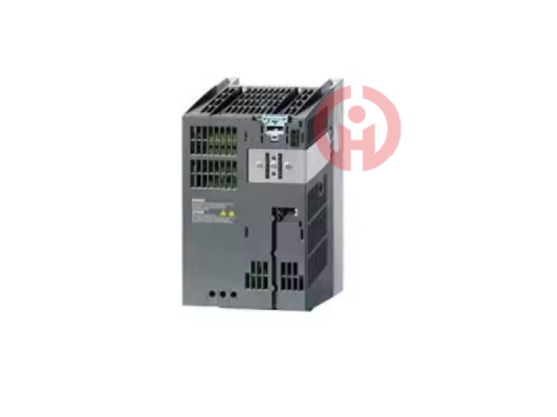
SIEMENS 6SE7041-8GK85-0HA0 Frequency Converter
Siemens inverter 6SE7041-8GK85-0HA0 is a high-performance drive solution, especially suitable for movements that require frequent changes in speed or direction of rotation, and occasions that require electric braking.
Related products

Product Introduction
6SE7041-8GK85-0HA0 trigger
The following identification data can be read out through SFC51 "RDSYSST":. Requirements: Use configuration package FM353V2.1 or configuration package FM354V2.1 and STEP7 version V3.1 or higher. If SM374 is used as a 16-channel output module, configure a 16-channel output module-use: SM322: 6ES7322-1BH01-0AA0, 6ES7134-4GB50-0AB02AII2DMU
At present, there is a lack of high-quality IGBT modules in China, and almost all of them are imported. The insulated gate bipolar transistor (IGBT) is the youngest in the high-voltage switch family. A 15V high-impedance voltage source can conveniently control the current flow device, thereby achieving high current control with lower control power. The working principle and function of IGBT in easy-to-understand way: IGBT is a switch, which is either on or off. How to control its on or off depends on the voltage of the gate-source. When +12V (greater than 6V, generally 12V to 15V) is added to the gate-source, the IGBT is turned on. When no voltage is added to the gate-source or a negative voltage is added, the IGBT is turned off. The purpose of adding negative voltage is to ensure reliable shutdown. IGBT does not have the function of amplifying voltage. It can be regarded as a wire when it is turned on and as an open circuit when it is turned off. 6RA8031-6FS22-0AA0
6RA8031-6FV62-0AA0
6RA8031-6GS22-0AA0
6RA8031-6GV62-0AA0
6RA8075-2FS22-0AP0
6RA8075-2FV62-0AP0
6RA8075-6DS22-0AA0
6RA8075-6DV62-0AA0
6RA80 75-6FS22-0AA0
6RA8075-6FV62-0AA0
6RA8075-6GS22-0AA0
6RA8075-6GV62-0AA0
6SE7033-7EG84-1JF0 driver board
6SE7035-1EJ84-1JC0 driver board
6SE7090-0XX84-6AD5 control board
6SY7000-0AC07 operation instructions
Hall sensor ES2000-9725
A5E00161042 power board
6SE7014-0TP50 operation instructions
6SL3353-6TE33-8AA3 fiber board
6SE7038-6GK84-1JC2 trigger board
6SE7036-5GK84-1JC2 driver board
6SE7037-0EK84-1JC0 driver board
6SE7037-0EK84-1JC1 driver board
6SE7037-0EK84-1JC2 driver board
6SE7041-2WL84-1JC1 driver board
6SE7041-2WL84-1 JC0 Operation Instructions
6SE7090-0XX84-2FA0-2FA0
6SL3353-6TE33-8AA3 Fiber Optic Board
It can be seen that although the fast opening and closing of IGBT is beneficial to shorten the switching time and reduce the switching loss, the too fast opening and closing is harmful under the large inductive load. When opening, there is the reverse recovery current of the freewheeling diode and the discharge current of the absorption capacitor. The faster the opening, the greater the peak current of the IGBT, and even rises sharply, causing damage to the IGBT or the freewheeling diode. When shutting down, the large inductive load will generate a high-frequency, high-amplitude and narrow-width spike voltage ldi/dt in the circuit with the fast opening and closing of the IGBT. The conventional overvoltage absorption circuit is difficult to absorb the spike voltage due to the limitation of the diode opening speed, so the vce rises sharply to produce overshoot. The IGBT will bear a higher dvce/dt impact, which may cause itself or other components in the circuit to be damaged due to overvoltage breakdown.
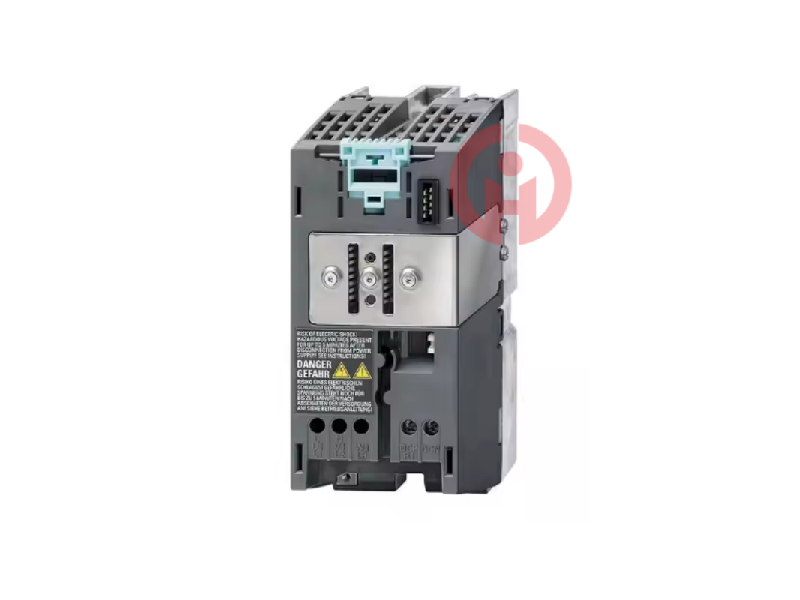
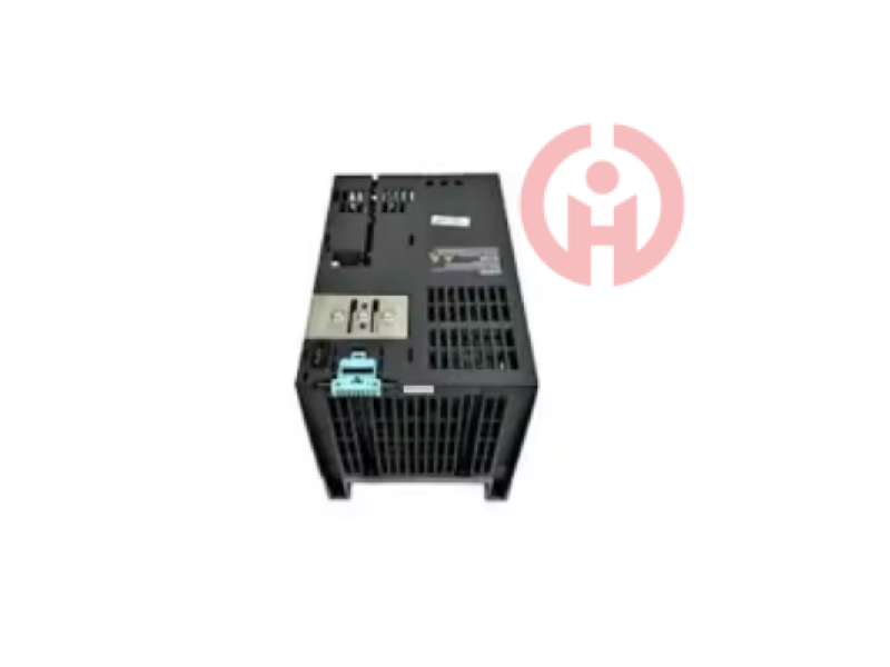
6SE7041-8GK85-0HA0 Trigger Operation Instructions 6SE7041-8GK85-0HA0 Trigger
The operating system calculates the bit address of the end position of a single element in the domain. 66: How to standardize and destandardize analog quantities? The following function blocks can be used: 1. In block FC164, x and y are both integers. CPU Yes, you can also use SM322-1HH01 when the load voltage is AC 24V.
IGBT drivers exb841, m57962 and hl402b can meet the above requirements. However, these drivers cannot block pulses. If no measures are taken, the soft shutdown protection will be performed once per cycle if the fault does not disappear. The heat accumulation generated in this way will still cause damage to the IGBT. For this purpose, the fault detection output of the driver can be used to block the gate pulse through an optocoupler, or the operating frequency can be reduced to below 1hz, and automatically restored to the normal operating frequency when the fault disappears.
Siemens ET200S module 6ES71936AR000AA0 line adapter BA 2×RJ45
Siemens ET200S module 6ES71936AF000AA0 line adapter BA 2×FC quick-connect
Siemens ET200S module 6ES71936AP000AA0 line adapter BA 2×SCRJ fiber
Siemens ET200S module 6ES71936AP400AA0 line adapter BA 1×SCRJ fiber/1×FC quick-connect
Siemens ET200S module 6ES71936AP200AA0 line adapter BA 1×SCRJ fiber/1×RJ45
Siemens ET200S module 6ES71936AG000AA0 line adapter BA 2×LC glass fiber, Optical fiber long distance 2KM
As shown in Figure 6, the IGBT driver module M57962L has a built-in protection function. When the detection circuit detects that the detection input terminal 1 is at a high level of 15V, it is determined to be a current fault, and the gate shutdown circuit is immediately started, and the output terminal 5 is set to a low level to cut off the IGBT. At the same time, the error signal is output to make the fault output terminal 8 low level to drive the external protection circuit to work, and the drive signal is blocked after a delay of 8~10μs, which can well achieve overcurrent protection. After a delay of 1~2ms, if the input terminal is detected to be at a high level, the M57962L is reset to the initial state.
6SE7041-8GK85-0HA0 Trigger Operation Instructions 6SE7041-8GK85-0HA0 Trigger
6ES7352-5AH00-0AE0 has M-type sinking output, which is only available when a plug-in resistor is added to each output terminal. The specification of the plug-in resistor is: 2,2kOhm/0,5W. Make sure there is a short-circuit connection in the switch box. MMC can be used as a load memory or portable storage medium. CPU312, CPU312IFM, CPU312C and CPU313 can only be used in single-rack module configuration 15: How to configure direct data exchange (inter-node communication) between two CPU modules that have been configured as DP slaves?
IGBT is a four-layer structure, so that there is a parasitic thyristor in the body, and the equivalent circuit is shown in Figure 4. There is a body region short-circuit resistor RS between the base and emitter of the npn tube, and the lateral hole flow in the p-type body region will produce a certain voltage drop, which is equivalent to a positive bias voltage for j3. Within the specified range, this positive bias voltage is not large, and the NPN tube will not conduct. When IC is greater than a certain level, the positive bias voltage is enough to turn on the NPN tube, and then the NPN and PNP tubes are in saturation, so the parasitic thyristor is turned on and the gate loses its control function, which is the holding effect. It increases the IC, causing excessive power consumption and even device damage. The temperature rise will cause the ICM of the IGBT to be held seriously. Terminal board 6RY1803-0GA00
A5E00825001 driver board
IGD trigger board FS300R12KE3_S1
Communication component 6SL3350-6TK00-0EA0
6SL3353-6TE32-1AA3 fiber board
Storage module 6DD1610-0AG1
6SE7090-0XX84-2FB0-2FBO
Power unit 6SL3352-1AE32-1AA1
Power unit 6SL3352-1AE32-1AA1
Display panel 6SL3055-0AA00-4BA0
6SL3353-3AE32-1AA0 data board
SK KT213/16E thyristor module
6SY7000-0AD07 inverter capacitor group
6RY1703-1HD01 common faults
Power board C98043-A7020-L4
6SE7022-6TC84-1HF3 power board
6SE7033-8EE85-0AA0 feedback unit
In the dynamic process of IGBT shutdown, if the dvce/dt is higher, the displacement current cj2dvce/dt caused in the j2 junction will be larger. When this current flows through the body short-circuit resistor RS, it can generate a forward bias voltage sufficient to turn on the npn transistor, satisfying the conditions for the parasitic thyristor to turn on and hold, forming a dynamic holding effect. The increase in temperature will increase the risk of dynamic holding effect of IGBT.
6SE7041-8GK85-0HA0 Trigger Operation Instructions 6SE7041-8GK85-0HA0 Trigger
71: For analog modules, how to handle unused channels? ???? If the module has MANA: short-circuit all unused channels' M- to MANA, if possible, connect MANA to the ground pole, set the module's measurement mode to: 0-20/+-20mA. Short-circuit unused COMP+/COMP-. IC+/IC- can remain floating. The * counting frequency of the 32-bit high-speed up/down counter is 30kHz, which can count two pulse trains of the incremental encoder with a difference of 90. When the count value is equal to the set value or the count direction changes, an interrupt is generated, and the output can be operated in time in the interrupt program. 3) In the case of simulation. For example, FM357-2 is ready to run without a driver. Switch output template SM322, slot 5, address 4--7; one switch output: limited alarm. Almost all S5/S7 analog input devices still work in a complex way, i.e. all channels are plugged into only one AD converter in sequence. This principle also applies to the constant current that is necessary to read the impedance. Therefore, the current flowing through the resistor to be read is only used for short-term readings. For an SM331-7KF02-0AB0 with a selected interface suppression "50Hz" and 8 parameterized channels, this means that the current will flow approximately every 180ms, and each time the impedance can be read for 20ms.
I think you'll find our product offers great value for money!
It's my pleasure to introduce our latest product, which will be a great addition to your current offerings!
We're thrilled to introduce you to our latest product, which we believe will meet your needs perfectly!
We believe this product can help to expand your market share. We look forward to the opportunity to work with you!
We sincerely welcome your calls and consultations and provide you with quality service 24 hours a day!
· Many products are not yet on the shelves please contact us for more products.
· If there is inconsistency between the product model and the display picture, the model shall prevail, please contact us for specific product pictures, we will arrange to take pictures in the warehouse to confirm!
.Technical Team Service Hotline:wujinghan102@gmail.com +86 13376990653
csyili980622@gmail.com +86 13306931261

