

Overview of Marine Valves
Valves are control components in fluid transportation systems, with functions such as cutoff, regulation,
diversion, prevention of backflow, stabilization, diversion, or overflow pressure relief. Valves used in fluid
control systems have a wide variety of varieties and specifications, from the simplest globe valves to various
valves used in extremely complex self-control systems. Valves can be used to control the flow of various types
of fluids such as air, water, steam, various corrosive media, mud, oil, liquid metals, and radioactive media. It is
commonly used on ships to control fluids such as compressed air, cooling water, hydraulic oil, etc.
1、 Classification of valves
There are many types of valves, and there are multiple classification methods. They are generally divided
into:
1. Cut off valves: mainly used to cut off or connect medium flow. Including gate valves, globe valves,
diaphragm valves, and plug valves
2. Regulating valves: mainly used to regulate the flow rate, pressure, etc. of the medium. Including regulating
valves, throttle valves, pressure reducing valves, etc.
3. Check valves: used to prevent medium backflow. Including check valves of various structures.
4. Diverter valves: used for distributing, separating, or mixing media. Including various structures of
distribution valves and drain valves.
5. Safety valves: used for overpressure safety protection. Including various types of safety valves.
2、 Introduction to commonly used valves for ships
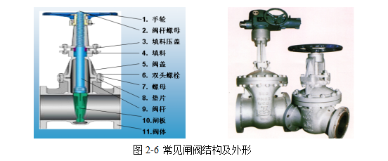
1. Gate valve:
Gate valve refers to a valve whose opening and closing body (valve plate) is driven by the valve stem to
move the sealing surface of the valve seat up and down, which can connect or cut off the passage of fluid.
When the valve is partially opened, eddy currents are generated on the back of the gate, which can easily
cause erosion and vibration of the gate, and also damage the sealing surface of the valve seat, making repair
difficult. Gate valves are usually suitable for working conditions that do not require frequent opening and
closing, and keep the gate fully open or closed. Not suitable for use as a regulator or throttle. As shown in
Figure 2-6.
2. Globe valve and throttle valve
Both globe valves and throttle valves are downward closing valves, and the opening and closing components
(valve discs) are driven by the valve stem and move up and down along the axis of the valve seat to open and
close the valve. The axis of the valve stem of the globe valve is perpendicular to the sealing surface of the
valve seat, and it is opened and closed by driving the up and down movement of the valve core. Once it is in
the open state, there is no longer contact between its valve seat and valve disc sealing surface, and it has a
very reliable cutting action, so its sealing surface has less mechanical wear. As the valve seat and valve disc
of most globe valves are relatively easy to repair or replace, there is no need to remove the entire valve from
the pipeline when replacing the sealing element. This is very suitable for situations where the valve and
pipeline are welded together.
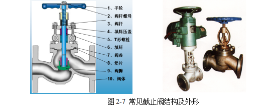
The structure of throttle valves and globe valves is basically the same, except for the shape of the valve
disc: the valve disc of globe valves is disc-shaped, while the valve disc of throttle valves is mostly conical and
streamlined, which is particularly suitable for throttling. It can change the cross-sectional area of the channel
to regulate the flow rate and pressure of the medium. The flow direction of the medium through this type of
valve changes, resulting in a higher flow resistance of the valve. In addition, introducing fluid from the lower
part of the valve core is called forward installation, and introducing it from the upper part of the valve core is
called reverse installation. During forward installation, the valve is easy to open and difficult to close, while
during reverse installation, the valve is tightly closed and difficult to open. Such valves are generally forward
installed. As shown in Figure 2-7.
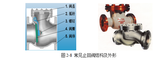
3. Check valve
A check valve refers to a valve that automatically opens and closes the valve disc based on the flow of the
medium itself, used to prevent the backflow of the medium. Its function
It only allows the medium to flow in one direction and prevents directional flow. Usually, this type of valve
works automatically, and under the pressure of fluid flowing in one direction, the valve disc opens; When the
fluid flows in the opposite direction, the pressure of the fluid and the self weight of the valve disc act on the
valve seat, thereby cutting off the flow. Including swing check valves and lift check valves. As shown in Figure
2-8.
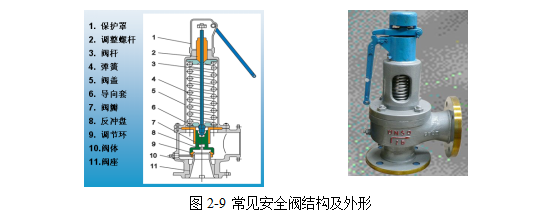
4. Safety valve
A safety valve is an automatic valve that uses the pressure of the medium itself to discharge a certain
amount of fluid without any external force, in order to prevent the pressure inside the system from exceeding
the predetermined safety value. After the pressure returns to a safe value, the valve will automatically close
to prevent the medium from continuing to flow out. The working principle of a safety valve is based on force
balance. Once the pressure on the valve disc exceeds the set pressure of the spring, the valve disc will be
pushed open by this pressure, and the gas (liquid) inside the pressure vessel will be discharged to reduce
the pressure inside the pressure vessel. As shown in Figure 2-9.
The selection of safety valves requires high sensitivity, specified discharge pressure, strength, sealing, safety
and reliability during use, allowable deviation and limit values for operating performance.
3、 Valve actuator device
Valve actuators are generally divided into two categories: pneumatic actuators and electric actuators
1. Valve pneumatic actuators are safe, reliable, low-cost, and easy to use and maintain, making them a major
branch of valve drive mechanisms. Pneumatic devices are commonly used in applications with
explosion-proof requirements. The valve pneumatic drive device uses a lower working pressure of the gas
source

The structural dimensions are not large, and the total thrust of the valve pneumatic drive device is also not
very large.
2. Electric actuators are generally composed of components such as motors, gearboxes, manual control
mechanisms, mechanical position indicator mechanisms, etc. Compared with other valve drive devices
electric drive devices have the characteristics of a wide range of power sources, fast and convenient
operation, and are easy to meet various control requirements. So, in valve drive devices, electric devices
dominate. As shown in Figure 2-10.
Valves have a wide range of applications on ships and often play a significant role. For example, in hydraulic
systems, valves can control the operation of the system; Valves also play an important role in maintaining the
normal operation of equipment in various piping systems in the cabin. However, compared to other products
valves are often overlooked. When installing machinery and equipment, people tend to focus on the main
machinery and equipment aspects while neglecting the installation of valves; Or selecting the wrong model
or specification of valve, etc. These practices will reduce the overall production efficiency or halt production
or cause various other accidents to occur. Therefore, the selection, installation, and use of valves must be
carefully and responsibly carried out, especially for the operation, production, and construction of modern
ships.
Knowledge Link - Ship Valve Operation Methods and Precautions
1. Opening and closing of manual valves
Manual valves are the most widely used valves, and their handwheel or handle is designed according to
ordinary human labor, considering the strength of the sealing surface and the necessary closing force.
Some people are accustomed to using a wrench, so they should be strictly careful not to apply too much
force, otherwise it is easy to damage the sealing surface or break the wrench or handle. When opening and
closing the valve, the force should be steady and not impact. Some components of high-pressure valves with
impact opening and closing have already considered that this impact force cannot be equivalent to that of
general valves.
For steam valves, they should be preheated and condensed water should be drained before opening. When
opening, they should be opened as slowly as possible to avoid water hammer. After the valve is fully opened
the handwheel should be turned back slightly to tighten the threads tightly to prevent loosening and damage.
For open stem valves, remember the position of the valve stem when fully open and fully closed to avoid
hitting the top dead center when fully open. And it is convenient to check whether it is normal when fully
closed. If the valve handle falls off or large debris is embedded between the valve core seals, the position of
the valve stem will change when fully closed.
When the pipeline is first used, there is a lot of dirt inside. The valve can be slightly opened to use the
high-speed flow of the medium to wash it away, then gently closed (cannot be quickly or abruptly closed
to prevent residual impurities from damaging the sealing surface), and opened again. Repeat this process
multiple times to flush out the dirt before returning to normal operation. Normally open valves may have
dirt adhered to the sealing surface. When closing, the above method should be used to flush it clean before
formally closing it tightly. If the handwheel or handle is damaged or lost, it should be immediately equipped
and cannot be replaced by a flexible wrench to avoid damaging the valve stem square, causing ineffective
opening and closing, and leading to accidents in production. Some media may cool down after the valve is
closed, causing the valve to contract. The operator should close it again at an appropriate time to ensure
that there are no fine gaps on the sealing surface. Otherwise, the medium will flow through the gaps at high
speed, which can easily erode the sealing surface.
2. General precautions
Valves with temperatures above 200 ℃ are installed at room temperature. However, after normal use, the
temperature increases, causing the bolts to expand and the gap to widen. Therefore, they must be tightened
again, which is called "hot tightening". Operators should pay attention to this work, otherwise leakage may
occur.
When the weather is cold and the water valve is closed for a long time, the accumulated water behind the
valve should be drained. After the steam valve stops, condensate should also be removed. The valve bottom
is like a plug, it can be opened for drainage. Non metallic valves, some are hard and brittle, while others have
lower strength. When operating, the opening and closing force should not be too strong, especially not too
forceful. Also pay attention to avoiding object collisions.
When using a new valve, do not press the packing too tightly to prevent leakage, in order to avoid excessive
pressure on the valve stem, accelerate wear, and make opening and closing difficult. When operating, if it is
found that the operation is too difficult, such as the packing being too tight, it can be relaxed appropriately.
If the valve stem is skewed, personnel should be notified for repair. Some valves, when in the closed state
have their closing components expand due to heat, causing difficulty in opening; If it is necessary to open at
this time, loosen the valve cover thread by half a turn to one turn to relieve the stress on the valve stem, and
then turn the handwheel.


